AIDC Network Solution Based On IB Switches
With the continuous progress of technology, high-performance computing in intelligent computing centers has been widely applied in various fields, especially in large-scale scientific computing and big data analysis.
Using InfiniBand network and QM9790 IB switch as the core device, this device has powerful functions with 64 400G ports.
1: 1. Non blocking network architecture.
Computing network architecture is a balanced, full fat tree.
Reaching the top level through rail optimized technology.
Supports the latest SHARPv3 features.
Spine to Leaf Cascade:
In the cascade design from Spine to Leaf, we focus on optimizing network connection performance to avoid any situations that may cause network congestion. Through reasonable configuration, we can achieve or approach the theoretical maximum transmission rate peak between switches, thereby ensuring the efficient execution of computing tasks.
Each Leaf uses 400G fiber optic to connect Spine. Each Leaf is connected to each Spine using 400G fiber optic.
Leaf linked to server layer:
In the connection from Leaf to the server layer, we adopted Superpod’s solution and implemented the function of track optimization. Through this approach, we ensure that the communication rate between GPUs is not affected by physical connections, thus achieving optimal performance. This optimization measure can maximize the speed of data transmission and accelerate the calculation process.
In the Leaf server connection, we divide into multiple groups (SU), each consisting of 8 Leafs and 32 servers. Each server’s 8 network cards are connected to 8 Leaf via a 400G fiber optic cable. This flexible configuration allows our network architecture to adapt to different computing needs, enabling efficient processing of both large-scale parallel computing tasks and highly complex computing tasks on this platform.
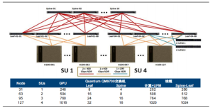
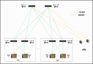
Figure 1 Computing Network Architecture Diagram
Storage Network Architecture
Using InfiniBand network and QM9790 IB switch as the core device, this device has powerful functions with 64 400G ports.
The storage network architecture is a full fat tree.
Independently from computational structures to maximize storage and application performance.
It is flexible and can scale to meet specific capacity and bandwidth requirements.
1: 1. Non blocking network architecture. Or a networking method with a 3:5 convergence ratio (Leaf uplink 24, downlink 40).
Meet the requirement for a single storage device to be equipped with a 1 * 400G (CX7) or 2 * 200G (CX6, CX7) network card.
Spine to Leaf Cascade:
We ensure that each Leaf switch has the same number of ports connected to the Spine switch, which can reduce the possibility of network congestion and enable the performance peak to reach or approach the theoretical maximum transmission rate between switches. This design ensures smooth data flow and efficient storage access.
On the Spine Leaf end, each Leaf uses 400G fiber optic to connect to the Spine. In addition, if there are remaining ports, they can be used to access the UFM server. This connection method ensures the full utilization of fiber optic resources and the stability of the network.
Leaf linked to server layer:
On the Leaf GPU server side, in order to ensure the stability and efficiency of data transmission, Leaf uses 400G fiber optic to connect each GPU server.
On the Leaf storage server side, we adopt different connection methods for different types of storage devices. If using a Connext-7 network card, we use a 400G to 200G split fiber patch cord with module connection; If using a Connext-6 network card, we will use a one in two cable connection from OSFP to 2 * QSFP56 HDR specifications. This design not only considers the compatibility of different devices, but also ensures the performance and stability of data transmission.
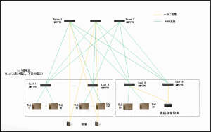
Figure 2 Storage Network Architecture Diagram
In band management network architecture
Using Ethernet and SN 4600C Ethernet switch as the core device, this device has powerful capabilities with 64 100G ports.
This network is used for node configuration, data movement, Internet access and services that other users must be able to access.
1: 1. Non blocking network architecture. Or a networking method with a convergence ratio of 4:5 (Leaf uplink 28, downlink 35).
The in band management network architecture is a full fat tree.
Spine to Leaf Cascade:
In the connection method from Spine to Leaf, we ensure that each Leaf switch is connected to an equal number of ports to reduce congestion risk and ensure that the peak transmission rate between switches can reach or approach the theoretical maximum value. Each Leaf switch is connected to Spine using 100G cables.
Leaf linked to server layer:
In the section that connects to the server layer, we configure multiple ports to connect various nodes (including GPU servers, storage devices, and management nodes). Each device is connected using a 100G finished cable to ensure stable data transmission and management operations.
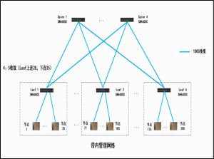
Figure 3 Architecture diagram of in band management network
Out of band management network architecture
Using Ethernet and SN 2201 Ethernet switch as the core device, this device has powerful capabilities with 48 1G ports.
The out of band management network connects all basic management controller (BMC) ports, as well as other devices that should be physically isolated from system users.
Using 1G access
Multiple Ethernet switches with 1G and 10G ports are required as Leaf layer devices, while multiple 10G Ethernet switches are equipped as Spine layer devices. This allows for access to multiple nodes at most.
Adopting 10G access
Multiple Ethernet switches with 10G and 100G ports are required as Leaf layer devices, while multiple 100G Ethernet switches are equipped as Spine layer devices. This allows for access to multiple nodes at most.
Spine to Leaf Cascade:
In the cascading section from Spine to Leaf, we ensure that each Leaf switch has exactly the same number of ports connected to the Spine switch. This design helps to reduce the risk of network congestion and ensure that the peak transmission rate between switches can reach or approach the theoretical maximum value. Each Leaf switch is connected to Spine using 10G or 100G finished cables.
Leaf linked to server layer:
We have configured multiple ports in the Leaf layer device to connect to the server layer, using 1G or 10G cables to connect various nodes, ensuring stable data transmission and management operations.
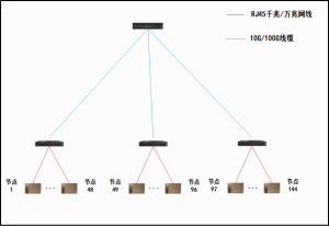
Figure 4 Architecture diagram of out of band management network
Jaguar-network IB value and advantages
⇘ Expert service
Professiona, comprehensive and rellable solution and service team, providing customers with hourly rapid response services